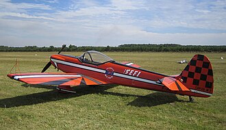
The aircraft was developed by French manufacturer Avions Mudry, with its design associated with Claude Piel and the company’s founder, Auguste Mudry. It emerged from the same broader design family as the two-seat Mudry CAP 10, but the CAP 20 was adapted for a single pilot and a more specialised competitive role. The aircraft subsequently served with the French Air Force’s aerobatic team, the Équipe de Voltige de l’Armée de l’Air, helping establish its place in French aerobatic aviation. The CAP 20 was not the final word in the family’s development: lighter versions and aircraft with revised wing designs followed, including the CAP 20L and CAP 21. These later designs helped pave the way for the more powerful CAP 230, CAP 231 and CAP 232 series.
Understanding the Mudry CAP 20 therefore requires more than listing its engine output or maximum speed. Its importance lies in the way it reflects the evolution of competition aerobatics, where designers must balance power, weight, aerodynamic efficiency, control response and structural strength. The aircraft also illustrates the difference between a machine that is capable of performing aerobatic manoeuvres and one that is optimised to excel in a demanding competition environment. Although the CAP 20 was a significant specialised aircraft, its development also revealed the limitations of its original configuration and encouraged further experimentation with lighter structures and improved wings. This article explores the aircraft’s origins, design, cockpit, powerplant, flight characteristics, variants, military use and lasting significance, followed by a technical specification table. Since measurements can differ between individual versions and historical references, figures are identified as representative rather than universal.
Development and Historical Background
The origins of the CAP 20 programme
The CAP 20 emerged from the French aviation industry’s continuing interest in purpose-built aerobatic aircraft during the second half of the twentieth century. Aerobatic flying had become increasingly specialised, with pilots performing precisely sequenced manoeuvres that required more than general-purpose flying skills. Aircraft designed for ordinary recreational use could sometimes perform limited aerobatic manoeuvres when appropriately approved, but competition pilots benefited from machines designed around a more demanding set of requirements. These included predictable control response, the ability to withstand significant positive and negative loads within approved limits, reliable engine operation during unusual attitudes, and an aerodynamic layout suited to repeated changes in pitch, roll and yaw.
The Mudry CAP 10 provided a useful starting point for this development. As a two-seat aerobatic trainer, it combined the ability to introduce pilots to aerobatic flying with a configuration suited to more advanced instruction. A single-seat derivative could eliminate the weight and space associated with a second occupant and allow the aircraft to be configured more directly for competition. The CAP 20 followed this approach, retaining the broad design philosophy of the CAP family while adopting a narrower, single-seat fuselage and other features intended for specialist aerobatic use. The resulting aircraft was not simply a CAP 10 with the passenger seat removed; it represented an effort to tailor the airframe to the different demands of solo competitive flying.
First flight and early production
Published references differ on some details of the CAP 20’s chronology, particularly when the initial prototype programme is compared with later production and lightweight derivatives. One widely reproduced account records the prototype’s first flight on 15 January 1976, followed by introduction of the production-oriented CAP 20 LS-200 in November of that year. The prototype reportedly used an engine rated at approximately 180 horsepower, while subsequent pre-production aircraft used a 200-horsepower powerplant. Other historical summaries describe earlier CAP 20 development and operational dates, so the dates should be understood in the context of the particular version being discussed rather than as a single timeline that applies identically to every CAP 20-family aircraft.
The production run of the original CAP 20 family was limited compared with the output of mass-produced trainers or general aviation aircraft. A commonly cited production summary lists twelve aircraft for the CAP 20 LS-200 designation over the period from November 1976 to July 1979, while other accounts group earlier CAP 20 versions separately. The small numbers are consistent with the aircraft’s specialised purpose: aerobatic competition machines are typically built for a narrow community of operators and pilots, and their value lies in their performance characteristics rather than in broad commercial utility. The CAP 20 was also part of an evolving programme in which experience with one design informed the next. Rather than remaining unchanged for decades, the aircraft family moved towards lighter structures and revised aerodynamic layouts as designers pursued improvements in competitive performance.
Design and Aerodynamic Configuration
Low-wing monoplane layout
The Mudry CAP 20 uses a low-wing monoplane configuration, a layout well suited to the visual and aerodynamic demands of aerobatic flying. Its wings are attached to the lower portion of the fuselage, creating a compact aircraft with a relatively clean external arrangement. A low-wing design does not automatically guarantee superior aerobatic performance, but the overall geometry can be optimised for the required balance of stability, control authority and manoeuvrability. For a competition aircraft, designers must consider how the wing behaves not only during ordinary level flight but also during steep turns, inverted flight, rapid rolling manoeuvres and transitions between different attitudes.
The original CAP 20 is described in technical accounts as having a cantilever wing, meaning that the wing is supported internally rather than by external bracing struts. Historical descriptions also identify an all-wood wing structure and a wooden fuselage, with selected components such as the engine cowling using laminated plastic or other materials. This construction approach reflected the engineering practices of its period and the design lineage from the CAP 10. Aerobatic aircraft must be light enough to achieve useful performance while retaining sufficient structural strength for repeated manoeuvres, so every major structural decision affects the aircraft’s overall character. Materials, spar design, wing geometry, surface finish and the distribution of mass all contribute to the balance between strength, weight and aerodynamic behaviour.
Wing design and control response
The wing is among the most important components of any aerobatic aircraft because it determines how lift is generated and how the aircraft responds to changes in angle of attack and airflow. In competition flying, pilots need an aircraft that responds accurately to control inputs and behaves consistently throughout a planned sequence. The CAP 20’s wing and control surfaces were intended to support this specialist role, but early experience also highlighted the difficulty of producing an aircraft that combined strong structure with low mass and light control forces. One historical French account describes the original CAP 20 as robust and stable but relatively heavy and demanding on the controls, which limited its competitiveness against more advanced designs.
This distinction is central to understanding the CAP 20’s place in aviation history. An aerobatic aircraft may be capable of completing demanding manoeuvres yet still be less effective in competition if it requires excessive effort from the pilot, loses energy more rapidly than its rivals, or lacks the desired response during rapid transitions. In aerobatics, pilots evaluate how an aircraft enters, maintains and exits a manoeuvre, how precisely it follows a commanded path, and how its handling remains consistent through the sequence. A design that is predictable and structurally robust can be valuable for training and demonstration, but competition success often depends on finer differences in handling and energy management. The CAP 20’s subsequent development illustrates how designers continued to refine these characteristics.
Fuselage, tail and landing gear
The CAP 20 has a conventional tailwheel landing gear arrangement, with fixed main landing gear and a tailwheel supporting the rear of the aircraft on the ground. This configuration was common among aerobatic aircraft of its era and was compatible with the aircraft’s compact construction. Tailwheel aircraft require specific handling techniques during taxiing, take-off and landing because directional control can be more sensitive than in many tricycle-gear designs. For aerobatic pilots, ground handling is only one part of the broader skill set, but a clear understanding of the aircraft’s behaviour on the runway remains essential.
The fuselage was designed around a single pilot seated in a narrow cockpit, with the engine mounted at the nose and the tail surfaces providing longitudinal and directional control. In a single-seat aircraft, cockpit space is necessarily limited, and designers must position the pilot, instruments and controls so that essential information can be read and control inputs made without unnecessary movement. The shape and internal structure of the fuselage also influence visibility, mass distribution and aerodynamic drag. Together, these elements create an aircraft that is visually compact and functionally focused: there is little accommodation for passengers or baggage because the design priorities are concentrated on the pilot, the engine, the control system and the structural requirements of aerobatic flight.
Engine and Propeller System
The Lycoming powerplant
The CAP 20 was powered by a horizontally opposed, air-cooled Lycoming piston engine. Many descriptions of the aircraft identify an injected Lycoming engine in the 200-horsepower class, commonly associated with the AEIO-360 family. This type of engine was appropriate for aerobatic operation because the fuel-injection and inverted-flight lubrication arrangements used in suitable configurations were designed to support operation during manoeuvres in which the aircraft may spend time inverted or experience unusual attitudes. The exact engine model and equipment depended on the particular aircraft and variant, so it is important not to assume that every CAP 20 carried identical equipment throughout its service life.
An output of around 200 horsepower gave the CAP 20 a substantial amount of power for a compact single-seat aircraft, but engine power alone does not determine aerobatic performance. The aircraft must also manage its mass efficiently, retain energy through manoeuvres and provide the pilot with appropriate control response. Power is especially important when recovering energy after vertical or climbing figures, while aerodynamic drag and the aircraft’s weight influence how quickly speed is gained or lost. A well-matched engine and airframe can therefore be more effective than a more powerful combination whose additional mass or drag offsets the engine’s benefits. The CAP 20’s development history demonstrates the importance of this balance, as later refinements focused not only on power but also on the wing and overall weight of the aircraft.
Propeller and engine management
The propeller converts engine power into thrust, and its characteristics affect how efficiently the aircraft accelerates and climbs across different operating conditions. Technical descriptions of the CAP 20 family refer to variable-pitch propeller arrangements on versions equipped for competition use. A controllable-pitch or constant-speed propeller allows the engine and propeller combination to operate more effectively across a wider range of flight conditions than a fixed-pitch system. The precise installation varies by model, so propeller specifications should be checked against the relevant aircraft records rather than applied indiscriminately to every CAP 20.
Aerobatic engine management also demands attention to temperature, fuel delivery, lubrication and engine limits. Pilots must account for the changing power requirements of each manoeuvre, avoid exceeding approved operating limits and ensure that the engine remains within its specified parameters. Fuel-injected, aerobatic-rated engines are engineered to address some of the challenges associated with unusual attitudes, but no equipment removes the need for disciplined operation and proper maintenance. The CAP 20 was built for a specialised flying environment in which reliable power delivery was essential, yet safe operation still depended on the individual aircraft’s approved configuration, service history and operating limitations.
Cockpit and Pilot Controls
A single-seat working environment
The CAP 20’s cockpit was designed for one pilot, reflecting the aircraft’s competition-focused role. Removing the second seat allowed the airframe and internal arrangement to be optimised around a single occupant, although a narrow cockpit necessarily places greater emphasis on ergonomics and efficient instrument placement. During aerobatic manoeuvres, the pilot may experience rapid changes in orientation and significant physical loads, so the cockpit must provide secure seating, accessible controls and clear indications of engine and flight conditions. The pilot also needs to maintain awareness of the aircraft’s attitude and energy state while preparing for the next figure in a sequence.
Unlike a touring aircraft, the CAP 20 has no practical emphasis on passenger comfort, baggage capacity or long-distance convenience. Its cockpit exists primarily to support precise control and safe execution of aerobatic manoeuvres. Instrumentation and equipment can differ between individual airframes, especially when aircraft have been restored, modified or prepared for different operating roles. For this reason, a historical description can explain the cockpit’s general purpose, but the specific equipment in any surviving aircraft should be verified individually.
Control precision and pilot workload
Aerobatic flying places demanding requirements on a pilot’s ability to coordinate the primary flight controls. Ailerons regulate roll, the elevator controls pitch, and the rudder supports directional control and coordination. The pilot must combine these inputs in a precise sequence to produce the intended manoeuvre, while simultaneously managing speed, engine power and the aircraft’s position relative to the horizon. In a competition environment, even small deviations from the intended flight path can affect the quality of a figure, making predictable handling and appropriate control forces particularly valuable.
Historical commentary on the CAP 20 suggests that the original aircraft’s relatively heavy handling was one of its limitations when compared with later competition designs. This does not mean the aircraft was unsuitable for aerobatics; rather, it illustrates that an aerobatic aircraft can be structurally capable yet still leave room for improvement in pilot workload and manoeuvre precision. The experience gained with the CAP 20 and its derivatives contributed to an ongoing process of design refinement, in which the relationship between wing geometry, airframe mass and control response became increasingly important.
Flight Characteristics and Aerobatic Role
Designed for manoeuvrability rather than transport
The CAP 20’s principal role was competition and demonstration aerobatics, not routine transportation. Its compact airframe, single-seat cockpit and dedicated control arrangement were chosen to support the requirements of a pilot performing a planned sequence of manoeuvres. Aerobatic flight involves far more than simply turning sharply or flying upside down. It requires accurate entry speeds, controlled changes in attitude, careful management of energy and consistent positioning so that each figure can be flown within the prescribed geometry. The aircraft must be capable of responding predictably to the pilot while remaining within its approved structural and aerodynamic limits.
The CAP 20’s historical reputation is mixed in a useful way: it was a purpose-built aerobatic aircraft, yet contemporary and retrospective accounts note that its weight and relatively heavy controls limited its competitive effectiveness. This is a reminder that the performance of a specialist aircraft should be assessed against the standards of its intended task, rather than only against general aviation machines. An aircraft may be robust and stable but still be outperformed by a lighter or more refined design in a discipline where rapid response and efficient energy retention are critical.
Speed, energy and manoeuvre planning
Published figures for the CAP 20 vary with the exact version and the source being consulted. Some descriptions list a maximum speed in the region of 280 kilometres per hour, while other specifications refer to different speeds or limits. Such numbers should not be treated as interchangeable: maximum level-flight speed, cruise speed, permitted manoeuvre speed and never-exceed speed are different quantities. A value reported for one variant may also be inappropriate for another, particularly when engine installations, weight, propeller configuration or airframe modifications differ.
For aerobatic aircraft, energy management is especially important because a manoeuvre can exchange speed for altitude and then convert altitude back into speed. Entering a figure too slowly may compromise its geometry or make it impossible to complete as planned, while entering too quickly can expose the aircraft to excessive loads or overspeed conditions. Pilots therefore operate according to approved limitations and the specific manoeuvre requirements, rather than relying on a general maximum-speed figure. The CAP 20’s performance must consequently be understood as part of a broader relationship between power, weight, drag, control response and approved operating limits.
Structural strength and operating limits
A competition aerobatic aircraft must be designed to withstand the loads associated with its intended manoeuvres, but structural strength is not unlimited. Aircraft are approved for defined operating categories and load-factor limits, and pilots must remain within the limits applicable to their individual aircraft. The CAP 20 and its derivatives appeared in different configurations, so a single load-factor figure should not be assumed to cover every version or subsequent modification. Historical specifications can help explain the design, but they are not a substitute for the approved flight manual or current airworthiness documentation.
Repeated aerobatic use also places demands on inspection and maintenance. The airframe, control linkages, engine mounts, landing gear and other structural elements must remain in suitable condition, with particular attention paid to the effects of repeated loading and vibration. Restored or modified aircraft may differ from their original factory configuration, making reliable records and inspection history especially important. For an aircraft intended to perform high-load manoeuvres, careful maintenance is inseparable from its performance capabilities.
Variants and Continued Development
The original CAP 20 family
The CAP 20 name covers more than one configuration. Historical summaries identify several early versions, including the CAP 20A, CAP 20B and CAP 20E, alongside the initial CAP 20. These designations reflect changes made as the aircraft family evolved, although the available summaries do not always present the variants in precisely the same way. The CAP 20E is associated with a more powerful engine installation in some accounts, while other versions were developed around changes to the wings or related structural features. When researching a particular surviving aircraft, its exact designation and modifications matter more than a generic family description.
The original CAP 20 provided the foundation for this process, but it was not the end point. Its service and competition experience highlighted the challenge of combining strength, acceptable handling forces and a competitive power-to-weight relationship. The following designs attempted to address those issues through changes to the structure and aerodynamics. The resulting family is best understood as a sequence of related aircraft rather than one unchanging model: each iteration incorporated lessons from the earlier design and moved towards a more specialised competition machine.
CAP 20L and CAP 20LS-200
The CAP 20L was a lightweight development of the original aircraft; the letter “L” is commonly associated with the French word léger, meaning “light”. Although its outward appearance remained recognisably related to the CAP 20, it incorporated meaningful structural and aerodynamic changes. Accounts describe a more angular wing planform, reduced dihedral and a different fuselage cross-section. The changes were intended to reduce weight and improve the aircraft’s suitability for competitive aerobatics, demonstrating that the designers were prepared to reconsider major features rather than simply increasing engine power.
The CAP 20LS-200 is commonly associated with a 200-horsepower Lycoming engine and a production phase beginning in late 1976. The lightweight concept was intended to improve the relationship between the engine’s output and the mass being moved through each manoeuvre. Even modest reductions in weight can influence climb performance, acceleration and the aircraft’s ability to retain useful energy. However, lightweight construction must preserve the structural strength and durability required for the aircraft’s intended operating category. The CAP 20L and CAP 20LS-200 therefore represent an important transition in the family’s development, moving from the original airframe towards a more refined competition-oriented design.
The CAP 21 and later aircraft
The CAP 21 followed the CAP 20L with a revised wing design and further changes intended to improve aerobatic performance. It is a related aircraft, not simply another name for the original CAP 20, and its dimensions and performance figures should not be transferred to the earlier model. Reference material for the CAP 21, for example, lists a different set of dimensions and a 200-horsepower Lycoming engine. This distinction is important when reading online specification tables, where data from related aircraft can sometimes appear under a shared family heading.
Further development led to the CAP 230, CAP 231 and CAP 232, which moved the family into a more powerful generation of competition aerobatic aircraft. The later aircraft adopted more powerful six-cylinder Lycoming engines and incorporated additional structural and aerodynamic development. The CAP 230/231/232 family is therefore part of the CAP 20’s broader legacy, but these later models are substantially different aircraft and should not be used as a source for the original CAP 20’s technical specifications. Their development illustrates the gradual evolution from a robust early single-seat aerobatic aircraft towards machines designed to meet increasingly demanding competition standards.
Service with the French Air Force
The Équipe de Voltige de l’Armée de l’Air
One of the CAP 20’s most notable roles was its association with the French Air Force aerobatic team, the Équipe de Voltige de l’Armée de l’Air (EVAA). The team’s purpose was to demonstrate advanced flying skills and represent French military aviation through precise aerobatic performances. An aircraft used for this role must be suitable for repeated training, predictable manoeuvres and demanding demonstrations, while also meeting the operational and maintenance requirements of a military organisation. The CAP 20 offered a French-designed platform for this specialised activity and formed part of the country’s broader effort to develop domestic expertise in aerobatic aircraft.
The experience gained through team operations also placed the aircraft within a practical environment where handling, reliability and maintenance were regularly evaluated. Demonstration pilots must practise sequences repeatedly and understand how the aircraft responds across a range of manoeuvres. This experience can expose design strengths as well as weaknesses, particularly when the aircraft is compared with newer machines. Historical accounts suggest that the original CAP 20 did not deliver the level of competitive performance its designers and operators hoped for, despite its sturdy construction and useful stability. The later development of the CAP 20L and CAP 21 reflects the continuing search for improvements in the aircraft’s overall handling and aerodynamic efficiency.
Military aerobatics and national aviation development
The CAP 20’s connection with the French Air Force also demonstrates how aerobatic aircraft can serve a role beyond sporting competition. Military demonstration teams require skilled pilots, structured training programmes and aircraft that can support consistent performances. The aircraft itself becomes part of a wider system involving technical staff, inspection schedules, pilot preparation and careful operational planning. Although the CAP 20 was not a combat aircraft, its military use placed it within a professional aviation environment where performance and reliability were central considerations.
Its development was also part of a longer French tradition of designing aircraft for specialist flying roles. The CAP family helped bridge the gap between two-seat aerobatic trainers and dedicated single-seat competition aircraft, while later models extended the concept into more powerful designs. In that sense, the CAP 20’s historical importance does not depend solely on whether it became a dominant competition winner. It contributed to a continuing process of experimentation and improvement in which the experience of one aircraft helped inform the design of its successors.
Strengths and Limitations of the Mudry CAP 20
Principal strengths
The CAP 20’s most important strength was its purpose-built nature. Its single-seat arrangement and dedicated aerobatic configuration allowed the aircraft to focus on a task that differs considerably from ordinary private flying. Its Lycoming engine provided power appropriate to the class, while the conventional low-wing layout and fixed tailwheel landing gear reflected established design choices for specialist aircraft of the period. The aircraft was also part of a recognisable French design family whose subsequent members benefited from continued development.
Another strength was the knowledge generated by the aircraft’s operation and refinement. The CAP 20 offered a platform on which designers and pilots could evaluate the relationship between structural robustness, aircraft weight and handling characteristics. These lessons were relevant to the later CAP 20L and CAP 21, and the broader family eventually developed into more powerful competition aircraft. The original CAP 20 therefore has significance as an intermediate step in a design programme rather than as an isolated product.
Principal limitations
The most frequently discussed limitation was the aircraft’s weight and relatively heavy control feel. An aircraft may be capable of performing aerobatic manoeuvres but still be less competitive if it requires greater pilot effort or loses energy less efficiently than its rivals. In a discipline where small differences in control precision and manoeuvre execution matter, these characteristics can affect the overall quality of a performance. Historical commentary on the CAP 20 indicates that these issues encouraged designers to pursue lighter structures and improved wing designs.
The CAP 20’s relatively limited production is another consideration when comparing it with more widely used aircraft. A small fleet can make individual examples historically interesting, but it can also complicate efforts to find reliable documentation, replacement components and specialists familiar with a particular airframe. The condition of any surviving aircraft must therefore be assessed individually, especially if it has undergone restoration, modification or a change of ownership. Historical specifications are useful for understanding the design, but current maintenance and operating decisions must be based on the records and approved documentation for the actual aircraft.
The Mudry CAP 20’s Legacy in Aerobatic Aviation
The CAP 20’s legacy is most clearly visible in the development path that followed it. The original aircraft established a single-seat direction within the CAP family, while the CAP 20L explored weight reduction and revised geometry. The CAP 21 then introduced further aerodynamic changes, followed by the more powerful CAP 230, CAP 231 and CAP 232 series. These aircraft were not identical in design or performance, but they shared a broader ambition: to create purpose-built machines capable of meeting the increasingly demanding requirements of competitive aerobatic flying.
This progression illustrates an important principle of aircraft engineering: improvement is rarely achieved by changing only one component. Adding engine power can improve acceleration and climb, but it can also increase weight, alter balance and introduce new structural demands. Reducing mass may improve performance, but the structure must still withstand the loads associated with the intended manoeuvres. A revised wing can change the aircraft’s aerodynamic behaviour, yet the fuselage, control surfaces and pilot interface must work with it as a coherent system. The CAP 20 programme provides a useful historical example of how these factors interact during the development of a specialised aircraft.
For aviation enthusiasts, the CAP 20 remains interesting because it captures a particular moment in the evolution of French aerobatic design. It was developed for a demanding and highly specialised purpose, used in a military demonstration environment, and followed by designs that pursued further gains in performance. Its limitations are as instructive as its strengths, because they help explain why the CAP family continued to evolve instead of remaining with the original design.
Technical Specifications of the Mudry CAP 20
The following table summarises representative specifications for the original CAP 20, not the CAP 20L, CAP 21 or later CAP 230-series aircraft. Published figures differ between references and individual configurations. The values below should therefore be treated as historical reference data rather than as an operating specification for any particular surviving aircraft.
| Specification | Mudry CAP 20 — representative data |
|---|---|
| Country of origin | France |
| Manufacturer | Avions Mudry |
| Designer | Claude Piel, associated with the Mudry programme |
| Aircraft type | Single-seat aerobatic aircraft |
| Primary role | Competition and demonstration aerobatics |
| Crew | 1 pilot |
| First-flight date | Historical accounts vary by prototype and variant; one widely cited account gives 15 January 1976 |
| Powerplant | Lycoming horizontally opposed, air-cooled piston engine |
| Representative engine output | Approximately 200 hp (149 kW) |
| Propeller | Variable-pitch or controllable-pitch installation, depending on configuration |
| Wing configuration | Low-wing monoplane, cantilever wing |
| Structural construction | Primarily wooden structure in descriptions of the original design, with selected other materials |
| Landing gear | Fixed conventional tailwheel configuration |
| Length | Approximately 7.21 m in one commonly reproduced specification |
| Wingspan | Approximately 8.04 m in one commonly reproduced specification |
| Height | Approximately 2.00 m in one commonly reproduced specification |
| Wing area | Approximately 10.85 m² in one commonly reproduced specification |
| Maximum speed | Approximately 280 km/h in one historical reference; figures vary by source and configuration |
| Range | Approximately 400 km in one historical reference |
| Service association | French Air Force aerobatic team, EVAA |
| Related developments | CAP 20L, CAP 21, CAP 230, CAP 231 and CAP 232 |
Important specification note: These figures are not all confirmed across every version of the CAP 20, and some published sources disagree about dimensions, chronology and performance. In particular, the CAP 21 and later CAP aircraft have different specifications. The aircraft’s official documentation and individual airframe records should take precedence over general historical tables for maintenance, restoration or flight operations.
Conclusion
The Mudry CAP 20 occupies a distinctive place in the history of French aerobatic aviation. Developed as a single-seat derivative of the CAP 10 family, it was designed to meet the specialised demands of competition and demonstration flying. Its Lycoming-powered configuration, compact cockpit, low-wing layout and conventional landing gear reflected the requirements of an aircraft built for precision manoeuvres rather than passenger transport. Its association with the French Air Force’s aerobatic team further connected it with a professional environment in which aircraft handling, repeatability and reliability mattered.
The CAP 20 was not without limitations. Historical accounts describe it as robust and stable but relatively heavy, with control characteristics that left room for improvement in a competitive setting. Those shortcomings helped motivate the development of lighter versions and revised designs, including the CAP 20L and CAP 21. The later CAP 230, CAP 231 and CAP 232 extended the family’s evolution with more powerful engines and further refinements. Taken together, these aircraft show how a design can remain historically important even when its greatest contribution is the experience and engineering knowledge that it passes to the next generation.
For aviation historians and enthusiasts, the CAP 20 is therefore more than a set of technical measurements. It is an example of the compromises inherent in aerobatic aircraft design and of the continual effort to balance power, weight, structure and control response. Its story helps explain both the challenges of competitive aerobatics and the way specialised aircraft evolve through operational experience and successive engineering improvements.
